Rendering a Sprite
Since we are building a 2D game engine, a good starting point would be to ask how do we render (show) a sprite on screen. High level languages have libraries that make this task very easy. In javascript for example, we can just write:
drawImage(image, x, y)This would draw image at position x,y on
our canvas. With low-level languages, the process is more involved but
also more flexible. Since we care about performance, we want to make use
of hardware acceleration so we will be using OpenGL1 to
do our drawing. Rendering anything using OpenGL requires a lengthy and
cumbersome setup process, which our game engine will take care off on
behalf of the user. This setup will include the following steps:
- Creating an application window
- Setting up OpenGL parameters
- Loading resources (sprites)
For this tutorial it’s recomended to start with an empty Go project and fill in the code as you go through the tutorial. The completed code is here in case you need it.
Creating a Window
Creating a window is an operating system specific operation. Fortunately, there are many libraries that abstract the process away and also make it platform-agnostic. We will be using SDL2. SDL has been around for a while and has been used in Valve’s Source game engine. We will also be using SDL later to get low-level access to keyboard, mouse and gamepad inputs.
To setup a window using SDL we use:
window := sdl.CreateWindow(name, x, y, width, height, options)Which creates a window at screen position (x,y)
(measured in pixels). The window’s title bar will show name
and the window will have size (width, height). The
options parameter accepts a bunch of flags that can be OR’d
together like this:
var options uint32 = sdl.WINDOW_RESIZABLE | sdl.WINDOW_BORDERLESS | sdl.WINDOW_OPENGLThe option sdl.WINDOW_OPENGL is mandatory as we will be
using the window to draw with OpenGL.
Setting up OpenGL
OpenGL setup begins with creating an OpenGL context which is the internal data structures OpenGL needs to operate. The OpenGL context includes the frame buffer which is the data structure that stores pixels to be drawn on screen. The OpenGL context is associated with the window on which it is displayed and SDL can do the basic setup for us:
window.GLCreateContext()The created context needs to be initialized by running:
gl.Init()With this we are ready to start using OpenGL functions. To finish up our setup, we need to enable some OpenGL settings.
gl.BlendFunc(gl.SRC_ALPHA, gl.ONE_MINUS_SRC_ALPHA)
gl.Enable(gl.BLEND)
gl.Enable(gl.DEPTH_TEST)
gl.ClearColor(0.1, 0.1, 0.1, 1)
gl.Viewport(x, y, width, height)
These enable alpha testing, which lets us use transparent sprites
(sprites that have an alpha channel) and depth testing, which allows
sprites to occlude other sprites. We also set a default background color
and make it dark gray (values passed are red, green, blue and alpha and
values range between 0 and 1). Resist the urge to make it black.
Miss-configuration or bugs can make your sprites show up as black and by
having a gray background we can catch that (you can also use a color if
you like). The final configuration we need to provide is the viewport
which tells OpenGL where on the window to draw at. We provide the lower
left edge of a box and a width/height in pixels. Passing
0,0 and the width, height of our window will
let OpenGL write to the whole window but we are free to write to any
sub-portion of the window (we could, for example leave the left 25% of
the window unused to later draw a game UI). With these our setup is
complete. At this point our setup code creates an OpenGL window and
exits immediately.
Triangles
OpenGL renders geometric primitives the simplest of which is the triangle. Lets see how we can get a triangle to render. Firstly we need to provide the three vertices that makes up a triangle.
var triangle = [9]float32{
    0, 0, 0,
    1, 0, 0,
    0, 1, 0,
}
These vertices define a right angle triangle with a side length of 1 unit.
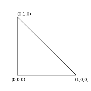
The values are intended to be used in tuples of 3 and each tuple
represents a width, height, depth (x,y,z) value. To render this
triangle, OpenGL expects this data in a specialized data structure
called a vertex buffer object (VBO). The VBO represents memory allocated
on the GPU so creating one is not as straightforward as calling
make(). We create a VBO like this:
var vbo uint32
gl.GenBuffers(1, &vbo)
gl.BindBuffer(gl.ARRAY_BUFFER, vbo)
gl.BufferData(gl.ARRAY_BUFFER, 4*len(triangle), gl.Ptr(&triangle[0]), gl.DYNAMIC_DRAW)
We can interpret the above invocation as follows:
GenBuffers creates the VBO which is represented by an
integer identifier (var vbo in the code). When we need to
use this VBO we must bind it using using this identifier which is what
we do with BindBuffer on the second line. The final line
does the actual allocation and copying of resources. Space is allocated
for 9 (len(triangle)) floats. We multiply the size by four
because a float is four bytes. The data from triangle is copied by
passing a pointer to our CPU-side array triangle3. The last parameter
gl.DYNAMIC_DRAW is a usage hint telling the OpenGL API how
this VBO is going to be used. DYNAMIC means we intend to
update this data. Passing STATIC would indicate that this
is data that will not update, like a static 3D model.
The last line reveals an important fact about OpenGL programming.
Notice that we don’t pass vbo to BufferData.
Instead BufferData operates on the last buffer bound
through BindBuffer. You can think of OpenGL as having an
internal set of global variables. When we call BufferData,
OpenGL looks into this internal state to find the currently bound buffer
and operates on that. This internal state does not respect locality, so
you could call BindBuffer in one function and
BufferData in another function.
Shaders
Our code so far sets up OpenGL and copies a triangle to the GPU. The next step is to tell the GPU how to render this triangle. This is done using shaders. Shaders are programs, written in C-style languages called shading languages that execute on the GPU. OpenGL’s shading language is (unimaginatively) called OpenGL Shading Language or GLSL4. There are two shaders we need write: a vertex shader and a fragment shader.
A vertex shader’s main input is the vertices that we pass in our vertex buffers. A vertex shader will be executed once for each vertex and will output the location of the passed vertex. How it computes this location depends on what we are trying to accomplish. In 3D applications the passed vertex location will have to be projected using math operations to create a perspective effect (where objects far away appear smaller than objects closer to the camera). In 2D applications, the vertex shader can be as simple as passing the original vertex position to the next stage in the GPU pipeline. Here is a minimal vertex shader:
#version 410
// shader input
layout (location=0) in vec3 vertex; // vertex position, comes from currently bound VBO

// shader program
void main() {
     gl_Position = vec4(vertex.x, vertex.y, vertex.z,1);
}
The input data of the shader (vertex) comes from the
currently bound vertex buffer. Since we can have multiple vertex
buffers, we need to tell OpenGL which one to use when running the
shader. This is done with:
gl.VertexAttribPointer(0, 3, gl.FLOAT, false, 0, nil)
gl.EnableVertexAttribArray(0)
This binds the current buffer to location 0 in the shader (notice the
0 in gl.VertexAttribPointer(0,... and
gl.EnableVertexAttribArray(0)). For this example we are
only using one buffer so we can do the matching of buffer to shader
location during our buffer setup, which now becomes:
var vbo uint32
gl.GenBuffers(1, &vbo)
gl.BindBuffer(gl.ARRAY_BUFFER, vbo)
gl.VertexAttribPointer(0, 3, gl.FLOAT, false, 0, nil)
gl.EnableVertexAttribArray(0)
gl.BufferData(gl.ARRAY_BUFFER, 4*len(triangle), gl.Ptr(&triangle[0]), gl.DYNAMIC_DRAW)
Since we have three vertices in our buffer the vertex shader will run
3 times. On each run it will simply pass the vertex to the next stage by
copying it to the OpenGL built-in variable gl_Position.
The next step is rasterization and it is a fixed step in the GPU
pipeline which means we can’t program it. Rasterization takes the
gl_Positions created in the vertex shader and turns them
into primitives. In our case we are drawing triangles so every three
gl_Positions become a triangle. It then figures out how
many pixels5 are covered by each triangle. This
depends on the triangle’s geometry and the resolution of our window so
our single triangle could end up creating hundreds of pixels6. The information from our vertices
is interpolated and passed to each pixel within the primitive so that if
a triangle covers multiple pixels, those pixels will have information to
work with. Right now the only information we have for each vertex is its
position (gl_Position) but later we will be passing more
information for each vertex and this interpolation step will become more
important.
The second shader we need to write is the fragment (or pixel) shader.
A fragment shader program runs once for each pixel created in the
rasterization step and computes the color for that pixel. Here we can do
calculations that simulate the appearance of various materials such as
mat, shiny and metallic and shade those materials differently depending
on the position of light sources in our game. For our example the
fragment shader simply paints all pixels pink. Notice that, unlike the
vertex shader, the fragment shader does not write to a built-in variable
but to a user-defined variable that has the out
specifier.
#version 410
out vec4 frag_colour;

void main() {
    frag_colour = vec4(1,0.8,0.9,1) ;
}
Shader Compilation
Unlike our Go code which compiles once and turns into an executable, shaders are compiled dynamically during runtime by our GPU’s driver. To compile our shaders we need more OpenGL invocations:
vertexShader := gl.CreateShader(gl.VERTEX_SHADER)
csource, free := gl.Strs(vertexShaderSource)
gl.ShaderSource(vertexShader, 1, csource, nil)
free()
gl.CompileShader(vertexShader)

fragmentShader := gl.CreateShader(gl.VERTEX_SHADER)
csource, free = gl.Strs(fragmentShaderSource)
gl.ShaderSource(fragmentShader, 1, csource, nil)
free()
gl.CompileShader(fragmentShader)
These calls create two shaders (vertex and fragment) and load the source from two Go strings7 (vertexShaderSource and fragmentShaderSource) that hold the shader code from the examples above. Finally, we compile each shader. It is possible to see compilation errors with some extra steps, see the example code for that. We then have to combine the two shaders into a single shader program:
prog := gl.CreateProgram()
gl.AttachShader(prog, vertexShader)
gl.AttachShader(prog, fragmentShader)
gl.LinkProgram(prog)
The shader is not enabled by default. We enable it using:
gl.UseProgram(prog)And with that we are ready to render.
Rendering
We now have our data in GPU memory and a shaders program so we are ready to render. We will setup a loop that will clear the screen and draw the data in the VBO using our shaders. Clearing the screen is done with:
gl.Clear(gl.COLOR_BUFFER_BIT | gl.DEPTH_BUFFER_BIT)This clears the color buffer (what is shown on screen) and the depth
buffer which tracks the back to front order for our geometry. The call
gl.Clear(gl.COLOR_BUFFER_BIT) will clear to whatever we set
with gl.ClearColor so if you run the program now you will
be seeing a background color show up. To draw our triangle we do:
gl.DrawArrays(gl.TRIANGLES, 0, 3)This draws the triangle to a hidden buffer which is not what our window is showing. We can update our window to show this buffer with:
window.GLSwap()This swaps hidden buffer with the shown buffer and the triangle appears on screen. This technique is called double buffering and by using it we avoid showing a buffer that is being rendered which can cause unwanted effects like screen tearing.
Recap
Lets recap what is happening so far.
Our program initializes a window and sets up OpenGL rendering. We
then create a Go array that holds three vertices of a triangle. We
create a GPU array called a VBO using the functions
GenBuffers and BindBuffer and we copy our
vertices from the Go array to the GPU array using
BufferData. We then setup a mapping that specifies that the
VBO will match a shader input at location 0 using the functions
VertexAttribPointer and
EnableVertexAttribArray.
The next step is to setup the code that will run on the GPU: our
shaders. We create a vertex shader that takes the VBO as input and just
passes the vertex data to the rasterizer. The rasterizer (which we do
not program) creates a triangle out of the three vertices and determines
which pixels lie in that triangle. Each pixel is then shaded by our
fragment shader. For now we output a fixed color for every pixel. These
shaders are compiled dynamically every time the program runs and are
combined into a shader program which has to be enabled (using
UseProgram).
The final step is to render. We create a loop that continuously
clears the screen and renders the triangle using
gl.DrawArrays. The process renders to an off-screen buffer
and that is swapped with the on-screen buffer on every frame.
The code up to this point is in the
01_rendering_a_sprite_part1 folder in the source repo. Play
around with this code and try to move the triangle around the screen and
change its shape by moving its vertices to new locations. Try adding
another triangle by adding three more vertices to the
triangle array. If you do that, also modify the call
gl.DrawArrays(gl.TRIANGLES, 0, 3) to
gl.DrawArrays(gl.TRIANGLES, 0, 6) which tells OpenGL to
draw 6 vertices instead of three.
Loading Images
The code for this part of the tutorial is here.
To render a image we first have to load the image from our disk to
RAM, then we need to copy it from RAM to the GPU. Loading from disk is
done using the Go image package.
imgFile, err := os.Open(imgFilename)
if err != nil {
    return 0
}
img, _, err := image.Decode(imgFile)
if err != nil {
    return 0
}
The image file is opened and then decoded into an Image
object. We then convert the image to our desired format which is RGBA
(red, green, blue and alpha).
rgba := image.NewRGBA(img.Bounds())
if rgba.Stride != rgba.Rect.Size().X*4 {
    return 0
}
draw.Draw(rgba, rgba.Bounds(), img, image.Point{0, 0}, draw.Src)
What these two steps achieve is they turn an image on disk, which can potentially be encoded or compressed, into an simple array of pixels where each pixel is a 4-tuple of RGBA values. This ‘raw’ representation is what we need to send over to the GPU.
In OpenGL parlance images are called textures. We create a texture like this:
var texture uint32
gl.GenTextures(1, &texture)
This is very similar to how we created the buffer that stores our vertices. One texture is created and its id (an int) is returned. We now need to bind it so we can modify it. If we create multiple textures, we need to bind the one we are modifying.
gl.BindTexture(gl.TEXTURE_2D, texture)We then copy the data from the rgba image to the texture
we just created. This is done with this, rather intimidating, call:
gl.TexImage2D(
    gl.TEXTURE_2D,
    0,
    gl.RGBA,
    int32(rgba.Rect.Size().X),
    int32(rgba.Rect.Size().Y),
    0,
    gl.RGBA,
    gl.UNSIGNED_BYTE,
    gl.Ptr(rgba.Pix))
This copies our data from the rgba array into a 2D
texture (TEXTURE_2D). We specify that the resulting texture
will store RGBA values with gl.RGBA and we also provide the
texture’s dimensions which we set to match the dimensions of the
original image. The last three parameters specify the source image
properties so that OpenGL knows how to convert it into a texture. We
specify that our image is RGBA (which is why we converted it before) and
what the data type is. The resulting image will use floating point for
each color but our image uses uint which we specify with
gl.UNSIGNED_BYTE. OpenGL will do the casting for us. The
final parameter is a pointer to the source data. OpenGL expects this to
be a one dimensional array with pixel values arranged like this
RGBARGBARGBARGBA... which is what how the internal storage
Pix of image.RGBA is organized. We now have
our image in GPU memory.
The final bit of setup is to specify how this texture is sampled.
Sampling is the process of retrieving values from the texture. Two
common sampling strategies are NEAREST and
LINEAR.
gl.TexParameteri(gl.TEXTURE_2D, gl.TEXTURE_MIN_FILTER, gl.NEAREST)
// or
gl.TexParameteri(gl.TEXTURE_2D, gl.TEXTURE_MIN_FILTER, gl.LINEAR)
Nearest sampling simply gets the texture pixel closest to the texture
location we specify. Linear interpolates nearby texture pixels and
returns the average. Linear interpolation is important in cases where a
small texture is mapped on large geometry or, equivalently, when the
geometry is viewed from a close distance (think of a game where you move
the camera very close to a wall). For 2D games we usually want
NEAREST sampling, especially if we are rendering pixel art
as linear sampling would blur our sprites.
Rendering the Texture
In OpenGL we use textures to color primitives like our triangle. To texture a triangle we need to provide texture coordinates for each triangle vertex. Texture coordinates, also commonly called uv values, are pairs of values between 0 and 1 (0-100%)8 that indicate locations within a texture. These match the geometry of the triangle to the texture image as seen in the figure below.
![]()
The above texture coordinates are A(0.25,0.25),
B(0.25,0.75) and C(0.5,0.25). In the above
example the region of the texture inside the triangle would appear on
the triangle when its rendered. In this example the texture coordinates
and the geometry of of the triangle have the same ratios with
AB=2*AC both for x,y coordinates and u,v (texture)
coordinates. This is not a requirement however. We could have easily
given C(1,1) as a texture coordinate and that would have
worked but the texture would appear warped on our triangle.
As with vertices, we need to send the texture coordinates to the GPU and the process is the same. We first define a Go array to hold the texture coordinates. There is one uv per vertex and the order that we define them defines the correspondence, that way the first vertex is associated to the first uv etc.
var uvs = [6]float32{
    0, 1,
    1, 1,
    0, 0,
}
We are using the full image here so uvs go from 0 to 100%. Also note that the uvs are inverted. That is because images are indexed starting from the top left (up is down!). We then create a vertex buffer and copy the array to the GPU.
var uvVbo
gl.GenBuffers(1, &uvVbo)
gl.BindBuffer(gl.ARRAY_BUFFER, uvVbo)
gl.BufferData(gl.ARRAY_BUFFER, 4*len(uvs), gl.Ptr(nil), gl.DYNAMIC_DRAW)
gl.VertexAttribPointer(1, 2, gl.FLOAT, false, 0, nil)
gl.EnableVertexAttribArray(1)
Notice that when we VertexAttribPointer and
EnableVertexAttribArray we pass location 1 since that’s
where the uvs will map in the shader (vertices are on location 0). Also,
the second parameter of VertexAttribPointer is 2 instead of
three as we are passing pairs of values, whereas for vertices it was 3.
We now need to update our shader to use the texture. The vertex shader
will receive the uvs in a new location (location=1) and can
access them through the uv variable.
#version 410
// shader input
layout (location=0) in vec3 vertex; // vertex position, comes from currently bound VBO
layout (location=1) in vec2 uv; // per-vertex texture coords

// shader output
out vec2 textureCoords;

// shader program
void main() {
    textureCoords = uv;
    gl_Position = vec4(vertex.x, vertex.y, vertex.z,1);
}
The vertex shader’s only responsibility it to pass those uvs to the
next stage of the pipeline. Unlike vertices, there is no bult-in
variable for this, so we define an output variable
out vec2 textureCoords; and copy uv there. Outputs of the
vertex shader become inputs of the fragment shader:
#version 410
in vec2 textureCoords;
out vec4 frag_colour;
uniform sampler2D tex;

void main() {
    frag_colour = texture(texture, textureCoords) ;
}
There are three important changes to our fragment shader. It now
takes texture coordinates, the output of the vertex shader, as input. We
denote that with an in specifier and make sure the variable
name matches in both shaders. Our shader now also has a new input
uniform sampler2D tex which is the texture it will read
from. Finally, instead of writing a fixed color as the output color, it
now reads the color of the texture at texture coords and uses that
instead. Accessing the texture is done through the built-in
texture function which takes care of sampling the texture
depending on the settings we specified.
A natural question to ask now is how does the output of the vertex shader, which runs once for each vertex, become input for the fragment shader that runs once for each pixel? The answer is that the pipeline step between the two, rasterization, creates more values using interpolation.
The only unknown now is how to pass the tex parameter to
the shader. Notice that it is specified as a uniform parameter. Uniform
parameters are specified once for the whole shader, unlike layout
parameters where we must pass one for each vertex. Its type,
sampler2D, indicates it is a texture. We associate textures
to shaders by binding them:
gl.ActiveTexture(gl.TEXTURE0)
gl.BindTexture(gl.TEXTURE_2D, texture)
Where texture is the texture id we created with
gl.GenTextures(1, &texture). Notice that the variable
name tex doesn’t come into play. This is because textures
are treated similarly to VBOs where we specify a location. In this case
our texture goes into texture unit 0 and the first
sampler2D variable in our shader will be bound to this
texture. If wanted to pass multiple textures we would do:
gl.ActiveTexture(gl.TEXTURE0)
gl.BindTexture(gl.TEXTURE_2D, aTexture)
gl.ActiveTexture(gl.TEXTURE1)
gl.BindTexture(gl.TEXTURE_2D, anotherTexture)
gl.ActiveTexture(gl.TEXTURE2)
gl.BindTexture(gl.TEXTURE_2D, moreTexture)
...
And define multiple samplers in our shader which are mapped in the order we define them:
uniform sampler2D tex;
uniform sampler2D texx;
uniform sampler2D texxx;
At this point if you run the code you should be seeing something like this:
![]()
A good exercise now would be to get the whole image to show. You will need to add an additional triangle to finish the rectangle and three more uvs to map the other half of the image to the new rectangle. Once that is done, expand the rectangle to fill the whole window. See the completed example if you are having problems.
https://www.opengl.org/. Vulkan (https://www.vulkan.org) would be another option. It is a lower-level API than OpenGL allowing for better control and possibly better performance but it is significantly more complex to set up and use.↩︎
https://www.libsdl.org↩︎
Here we pass a pointer to the 1st element in the array. If we where passing data from a slice we could have used the slice itself instead of it’s first element (
gl.Ptr(someSlice)).↩︎https://www.khronos.org/opengl/wiki/Core_Language_(GLSL).↩︎
For this introduction fragments and pixels are considered the same thing which is technically incorrect but not by much.↩︎
This is why increasing the resolution in a game is so impactful on the game’s performance.↩︎
We convert Go strings into C strings using gl.Strs(). OpenGL is a C API which is why some C weirdness (like having to free strings) sometimes creeps up. We try to abstract C-ness away from our engine users.↩︎
By using these normalized (0-1) values instead of width/height values in pixels we avoid needing to know the texture’s dimensions. This is a convenience when writing shader code but it also allows some optimizations like keeping low resolution copies of the same texture for use when rendering small objects.↩︎